Products\ ..
Renewable energy products
GRINOR provide the diverse of Solar panels and Win turbines. Each products have special features suitable with severe weather conditions and diversified demand. GRINOR are providing products of the leading technology such as Solar Panels and Wind Turbine.
 Solar panel |
 Wind turbine |
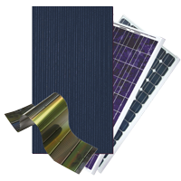
Solar Panels - PV module or Photovoltaic Panels
• Solar electricity is created by using Photovoltaic (PV)
technology by converting solar energy into solar electricity
from sunlight. Photovoltaic systems use sunlight to power
ordinary electrical equipment, for example, household
appliances, computers and lighting. The photovoltaic (PV)
process converts free solar energy - the most abundant energy
source on the planet - directly into solar power. Note that this
is not the familiar "passive" or Solar electricity thermal
technology used for space heating and hot water production.
• A PV cell consists of two or more thin layers of
semi-conducting material, most commonly silicon. When the
silicon is exposed to light, electrical charges are generated
and this can be conducted away by metal contacts as direct
current (DC). The electrical output from a single cell is small,
so multiple cells are connected together and encapsulated
(usually behind glass) to form a module (sometimes referred to
as a "panel"). The PV module is the principle building block of
a PV system and any number of modules can be connected together
to give the desired electrical output.
• PV equipment has no moving parts and as a result requires
minimal maintenance. It generates solar electricity without
producing emissions of greenhouse or any other gases, and its
operation is virtually silent.
Comparison table of various types of solar cells:
| Name | Descriptions |
Energy efficiency receive per 1sqm |
Surface area required for 1 kW power |
|
|
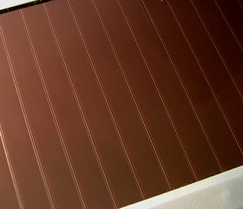
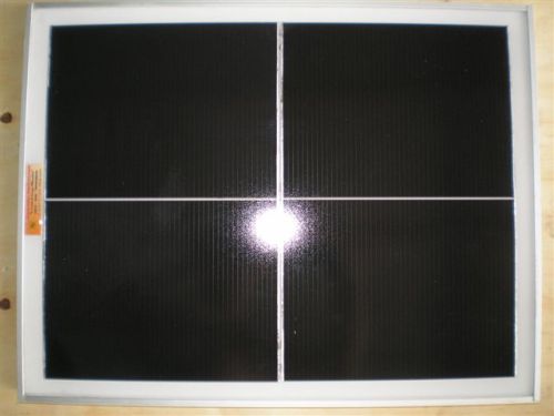
Amorphous silicon cells are composed of silicon atoms in a thin homogenous layer rather than a crystal structure. Amorphous silicon absorbs light more effectively than crystalline silicon, so the cells can be thinner. For this reason, amorphous silicon is also known as a "thin film" PV technology. Amorphous silicon can be deposited on a wide range of substrates, both rigid and flexible, which makes it ideal for curved surfaces and "fold-away" modules. Amorphous cells are, however, less efficient than crystalline based cells, with typical efficiencies of around 6%, but they are easier and therefore cheaper to produce. Their low cost makes them ideally suited for many applications where high efficiency is not required and low cost is important. One characteristic of amorphous solar cells is that their power output reduces over time, particularly during the first few months, after which time they are basically stable. The quoted output of an amorphous panel should be that produced after this stabilization |
10% |
 14-20 m˛ |
|
Cadmium Telluride
Copper Indium Diselenide |
Other Thin Films: A number of other promising materials such as Cadmium Telluride (CdTe) and Copper Indium Diselenide (CIS) are now being used for PV modules. The attraction of these technologies is that they can be manufactured by relatively inexpensive industrial processes, certainly in comparison to crystalline silicon technologies, yet they typically offer higher module efficiencies than amorphous silicon. New technologies based on the photosynthesis process are not yet on the market. |
16%
19% |
 12-17 m˛  9-11 m˛ |
|
|
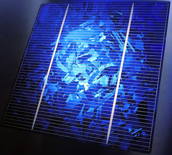
Made from cells cut from an ingot of melted and recrystallised silicon. In the manufacturing process, molten silicon is cast into ingots of polycrystalline silicon, these ingots are then saw-cut into very thin wafers and assembled into complete cells. Multi-crystalline cells are cheaper to produce than mono-crystalline ones, due to the simpler manufacturing process. However, they tend to be slightly less efficient, with average efficiencies of around 12%. They have a speckled crystal reflective appearance, and again need to be mounted in a rigid frame. |
20% |
 7.5-10 m˛ |
|
|
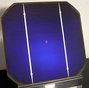
Made using cells saw-cut from a single cylindrical crystal of silicon, they are effectively a slice from a crystal. This is the most efficient of the photovoltaic (PV) technologies. The principle advantage of mono-crystalline cells are their high efficiencies, typically around 15%, although the manufacturing process required to produce mono-crystalline silicon is complicated, resulting in slightly higher costs than other technologies. In appearance, it will have a smooth texture and you will be able to see the thickness of the slice. They are also rigid and must be mounted in a rigid frame top protect them. |
25% |
 7-9 m˛ 6-7 m˛ |

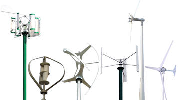
Wind turbine - Wind power unit (WPU)
- A wind turbine converts the energy of wind into kinetic energy. If the mechanical energy is used directly by machinery, such as pumping water, cutting lumber or grinding stones, the machine is called a windmill. If the mechanical energy is instead converted to electricity, the machine is called a wind generator, wind turbine, wind power unit (WPU), wind energy converter (WEC), or aero generator.
- Wind turbines can rotate about either a horizontal or vertical axis, the former being more common.

Horizontal axis wind turbines ():
• HAWT have the main rotor shaft and electrical
generator at the top of a tower, and must be pointed into the
wind. Small turbines are pointed by a simple wind vane, while
large turbines generally use a wind sensor coupled with a servo
motor. Most have a gearbox, which turns the slow rotation of the
blades into a quicker rotation that is more suitable to drive an
electrical generator.
• Since a tower produces turbulence behind it, the turbine is
usually pointed upwind of the tower. Turbine blades are made
stiff to prevent the blades from being pushed into the tower by
high winds. Additionally, the blades are placed a considerable
distance in front of the tower and are sometimes tilted forward
into the wind a small amount.
• Downwind machines have been built, despite the problem of
turbulence (mast wake), because they don't need an additional
mechanism for keeping them in line with the wind, and because in
high winds the blades can be allowed to bend which reduces their
swept area and thus their wind resistance. Since cyclic (that is
repetitive) turbulence may lead to fatigue failures most HAWTs
are upwind machines.

Vertical-axis wind turbines (VAWTs):
• Have the main rotor shaft arranged vertically. Key advantages
of this arrangement are that the turbine does not need to be
pointed into the wind to be effective. This is an advantage on
sites where the wind direction is highly variable.
• With a vertical axis, the generator and gearbox can be placed
near the ground, so the tower doesn't need to support it, and it
is more accessible for maintenance. Drawbacks are that some
designs produce pulsating torque.
• It is difficult to mount vertical-axis turbines on
towers[citation needed], meaning they are often installed nearer
to the base on which they rest, such as the ground or a building
rooftop. The wind speed is slower at a lower altitude, so less
wind energy is available for a given size turbine. Air flow near
the ground and other objects can create turbulent flow, which
can introduce issues of vibration, including noise and bearing
wear which may increase the maintenance or shorten the service
life. However, when a turbine is mounted on a rooftop, the
building generally redirects wind over the roof and this can
double the wind speed at the turbine. If the height of the
rooftop mounted turbine tower is approximately 50% of the
building height, this is near the optimum for maximum wind
energy and minimum wind turbulence.
Comparison table of two types of wind turbine:
| Advantages | Disadvantages | |
| HAWT |
Variable blade pitch, which gives the
turbine blades the optimum angle of attack. Allowing the
angle of attack to be remotely adjusted gives greater
control, so the turbine collects the maximum amount of
wind energy for the time of day and season. |
The tall towers and blades up to 45 meters long are difficult
to transport. Transportation can now amount to 20% of equipment costs. |
| VAWTs |
A massive tower structure is less frequently used, as
VAWTs are more frequently mounted with the lower bearing
mounted near the ground. |
A VAWT that uses guy-wires to hold it in place puts stress on the bottom bearing
as all the weight of the rotor is on the bearing. Guy wires attached to the top
bearing increase downward thrust in wind gusts. Solving this problem requires a
superstructure to hold a top bearing in place to eliminate the downward thrusts
of gust events in guy wired models. |
GRINOR provide the best products which have been awarded such international certificates:
 CE |
 RoHS |
|
 ISO9001 |